X4F103 SDK user guide#
Abstract#
The X4F103 SDK is a software (SW) component that handles the low level sensor communication with the NOVELDA X4F103 sensor and provides the user with a simple API. The SW is provided in C and can easily be ported to other platforms. This document will describe how to integrate and run the X4F103 SDK, how to port it to other platforms and walk through the sensor operation. A reference example project is provided built for Nordic Semiconductor´s nRF52840 to be run on their development kit in Zephyr OS. An explanation of how to build and run the reference project using west can be found in the readme file included in the SW. A description of how to build and run using VSCode can be found in X4F103 SDK example user guide.
Note
NOVELDA only supports running the X4F103 SDK as is. Custom implementations of direct control of the sensor through low level I2C/SPI commands are not supported.
Package content#
The NOVELDA SW folder will contain the following files:
- documents/
Release Notes - with version numbers and changes from previous releases.
Software User Guide (this document)
Software License
- source/
The X4F103 SDK.
Product specific algorithm blob and configuration.
- examples/
Usage example built for Zephyr OS on Nordic nrf52840DK.
X4F103 SDK operation#
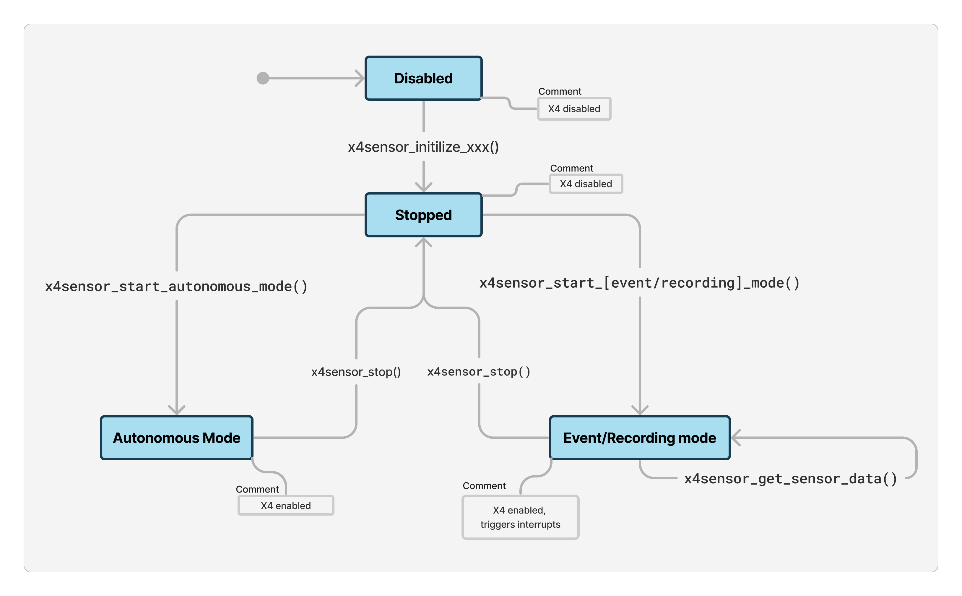
X4 Sensor states#
The X4F103 SDK features the following states of operation:
Operation State |
X4 Sensor Library |
X4 Sensor State |
|---|---|---|
Disabled |
The library is not initialized and no resources are allocated. |
|
Stopped |
The library is ready for further operation. The user may set additional configuration options like detection range and sensitivity and eventually start one of the operation modes. The chipinterface implementation may keep resources allocated, like driver handles. |
|
Autonomous mode |
No user interaction with the library is necessary. The sensor may be stopped at any time by calling x4sensor_stop(). |
|
Event mode/Recording mode |
The user must sample the interrupt signal of the sensor. Depending on the application architecture chipinterface_wait_for_interrupt() may be used (blocking) or another event-driven approach. After a rising edge of the interrupt line, x4sensor_get_sensor_data() must be called within 14 ms. This will eventually reset the interrupt line. The sensor may be stopped at any time by calling x4sensor_stop(). |
|
Test mode |
Same as Recording mode, but the sensor is configured in various states for regulatory compliance testing. |
|
The firmware is uploaded to the X4 sensor whenever the sensor state changes to “Enabled”. Firmware upload takes approximately 115 ms with I2C and 40 ms with SPI (32 MHz). During the first start, an oscillator measurement of the X4 is performed which takes about 150 ms in addition.
Note
After initialization, in the stopped operation state, the X4 enable pin is pulled low. The current consumption in this mode may increase to hundreds of micro amperes as described in the X4 errata.
API#
For API description and further details refer to novelda_x4sensor.h.
x4sensor_deinitialize() may be called at any time except when the sensor is not initialized.
x4sensor_set_range_cm() and x4sensor_set_sensitivity_level() may be called in Ready or Stopped state
Sensor initialization#
To initialize the sensor call x4sensor_initialize_i2c or x4sensor_initialize_spi depending on what interface you are using. The functions will enable the X4F103 sensor for a short time and read out meta information about the sensor. After that, the X4 will be powered down again. The initialization function parameters are a pointer to the X4 FW, located in x4_firmware.h and its size and a pointer to the sensor configuration blob and its size. Calling the deinitialize function will free up all resources allocated by X4F103 SDK and the underlying hardware interface. A new initialization is required to use the sensor after a deinit.
Reading sensor information#
After initialization it is possible to read out version numbers from the sensor. The x4sensor_get_info function returns a pointer to x4sensor_info_t which contains the following:
Sample ID - a unique identifier for the X4 IC.
Chip revision - The X4 revision number.
Algorithm Version - Major, minor and patch number of the algorithm version.
Other identifiers for the specific algorithm version.
Sensor configuration#
Sensor configuration can only be done in the Stopped state. Sensor configuration are optional steps which can be performed after initialization. It is possible to set the detection range and detection sensitivity. Any attempt to set a value outside the product range limits will result in an error.
Running the sensor#
From Idle the sensor can be started in either Autonomous, Event, Recording or Test mode.
Autonomous mode#
In this mode the sensor runs continuous proximity detection. The interrupt goes high and stays high whenever motion is detected and goes low and stays low when no motion is detected. The only way to leave autonomous mode is to call the sensor stop function which takes the sensor back to a PowerDown state.
The minimum time for the interrupt pin to stay high/low is given in the following table.
Algorithm |
Version |
FPS |
No-Presence -> Presence (IRQ low) |
Presence -> No-Presence (IRQ high) |
Min. ΔT1 |
Min. ΔT2 |
|---|---|---|---|---|---|---|
Proximity Outdoor |
0.10.50 |
32 |
4 frames |
4 frames |
125 ms |
125 ms |
Proximity Indoor |
0.10.50 |
8 |
1 frame |
2 frames |
125 ms |
250 ms |
Proximity LowPower |
0.10.50 |
1 |
1 frame |
1 frame |
1000 ms |
1000 ms |
Proximity LowPower |
0.10.50 |
2 |
1 frame |
1 frame |
500 ms |
500 ms |
Occupancy |
0.3.1 |
16 |
4 frames |
5 frames |
250 ms |
312.5 ms |
Occupancy |
0.7.8rc |
16 |
1 frame |
1 frame |
62.5 ms |
62.5 ms |
Occupancy |
0.x.x |
16 |
6 frames |
10 frames |
375 ms |
625 ms |
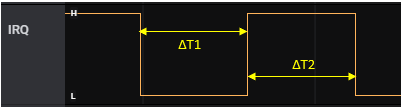
Interrupt line#
Event mode#
In this mode the sensor runs continuous proximity detection and the host may subscribe different events on startup:
X4SENSOR_EVENT_STATE_CHANGE: Notifies the host when proximity/occupancy was detected or the sensor state changed back to no detection.X4SENSOR_EVENT_PERIODIC_REPORT: Notifies the host after a fixed amount of frames. This can be used to implement a heart-beat (is the sensor still running?) or just a periodic update. The report interval is configured withx4sensor_set_periodic_report_interval().
Events are subscribed when starting the sensor with x4sensor_start_event_mode(). After an event the interrupt pin is raised and the host must read out the radar frame raw data within 14 milliseconds.
The host may use chipinterface_wait_for_interrupt() to wait for an interrupt in blocking mode or may use another approach.
After getting the interrupt, the user must call x4sensor_get_sensor_data() to read out the current frame from the sensor.
x4sensor_get_events()x4sensor_get_detection_state()x4sensor_get_distance_cluster()
Recording mode#
This mode is similar to event mode with a periodic report interval of 1. After each radar frame the interrupt pin is raised and the host must start to read out the radar frame within 14 milliseconds.
Proximity: 179 bytes
Occupancy: 403 bytes
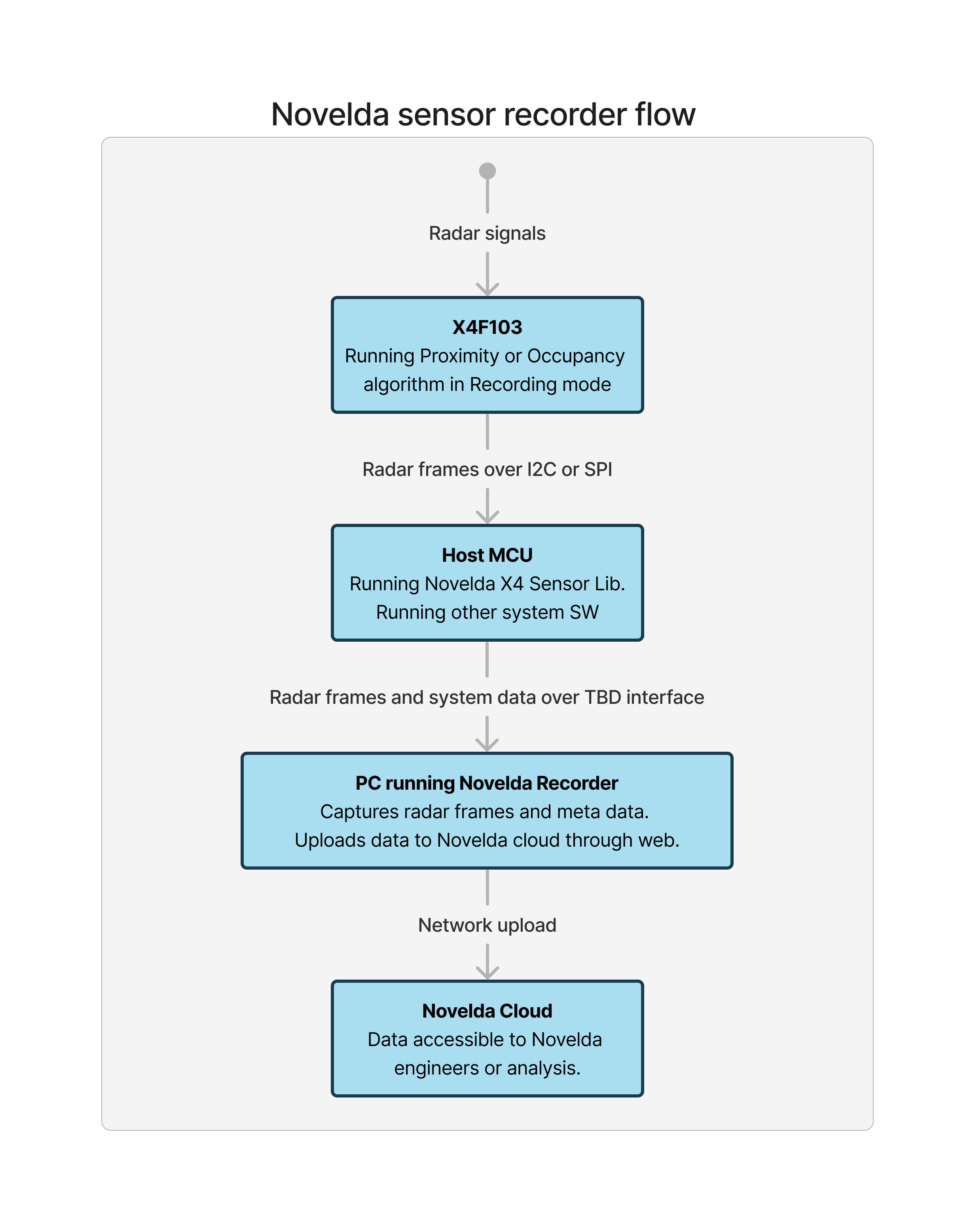
The radar frames can be forwarded from the host (in a user specific fashion) to a PC Tool called NOVELDA Recorder. This tool allows analysis of the sensor performance in the end product to verify proper integration as well as debugging should that be necessary. It is possible to enrich the radar data with application specific data (system status, timestamps, other sensor input), to help setting the radar sensor behaviour in the right context.
Test mode#
Same as Recording mode, but the sensor is configured in various states for regulatory compliance testing. See details further down.
Error handling#
Most functions of the X4F103 SDK API return either X4SENSOR_SUCCESS on success or an error code of type x4sensor_error_t otherwise. The specific error codes can be found in novelda_x4sensor.h.
In addition, and in case a function does not return an error but a different value, the last state can be retrieved with x4sensor_get_last_error().
Error codes can be converted to human-readable strings using x4sensor_convert_error_to_string().
x4sensor_error_t result = x4sensor_set_range_cm(999);
if (result != X4SENSOR_SUCCESS) {
    printf("X4Sensor error %d: %s", result, x4sensor_convert_error_to_string(result));
    return;
}
When observing an error after initialization, X4F103 SDK must be brought back into a valid state by calling x4sensor_deinitialize() followed by x4sensor_initialize_xxx().
Porting X4F103 SDK to other platforms#
The X4F103 SDK is designed to be easily portable between different host platforms from simple 8 bit microcontrollers to more complex systems.
Hardware connections#
Connect the following signals from the sensor to your MCU and make the appropriate HW configuration in your SW project.
Sensor Signal |
Description |
|---|---|
VDD |
Positive supply voltage, 1.8 V - 3.3 V |
GND |
Ground, 0V |
IRQ |
Sensor interrupt (sensor output), active high |
EN |
Sensor enable (sensor input), active high |
SDA |
I2C Data |
SCL |
I2C Clock |
Sensor Signal |
Description |
|---|---|
VDD |
Positive supply voltage, 1.8 V - 3.3 V |
GND |
Ground, 0V |
IRQ |
Sensor interrupt (sensor output), active high |
EN |
Sensor enable (sensor input), active high |
COPI |
Controller data output, sensor input |
CIPO |
Sensor data output, controller input |
SCLK |
SPI Clock |
CS |
SPI Chip Select |
Software build and usage#
Add the source folder to the include search paths in your project and compile the C source files as part of your project. The folder can also be copied into your SW project location if that is preferable.
Create novelda_chipinterface.c and implement your device specific functions as described in novelda_chipinterface.h.
Add sensor function calls to your project using the API in novelda_x4sensor.h as described earlier in this document.
The main file in the provided example project can be used as a reference.
The simplest way to start and run the NOVELDA sensor is shown in the code snippet below.
int main()
{
  x4sensor_initialize_i2c(data_i2c_driver, data_i2c_driver_size);
  x4sensor_set_range_cm(100); // optional
  x4sensor_set_sensitivity_level(3);// optional
  x4sensor_start_autonomous_mode();
  for (;;);
}
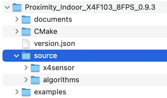
Source Folder in Reference Project#
Regulatory compliance test modes#
Regulatory compliance mode is similar to Recording mode with additional configuration required for various regulatory certification testing.
After entering test mode, x4sensor_stop() must be called to end the current mode before starting another test mode.
Test mode M1#
The radar transmitter is configured to send pulses continuously. The receiver is disabled and no data is read from the sensor. IRQ will thus never assert in this mode.
This mode is used to demonstrate the isolated emissions from the UWB transmitter, and the emissions generated by the digital circuitry needed to enable UWB transmission
Test mode M2#
Same as M1, but with the pulse generator in the transmitter disabled.
This mode demonstrates radiated emissions from digital circuitry used to enable operation of the UWB transmitter.
Test mode M3#
Autonomous operation, but with the pulse generator in the transmitter disabled.
This mode is used to demonstrate emissions from unintentional radiators not needed for, or generated by, UWB transmission.
Test mode normal#
Normal operation of the sensor, but with worst-case configuration for duty cycle.
This mode is used to demonstrate typical emissions from a module during normal operation.