Proximity#
Introduction#
The NOVELDA Proximity algorithm is designed to detect presence of people relative to a device for touchless human-machine interaction. Such devices can be vending machines, digital signage, appliances, smart toilets, etc.
The maximum detection range of the sensor corresponds approximately to a circular zone with a radius of 2 meters. The sensor has absolute range bounding which means that it has full sensitivity out to the configured range limit, and full rejection outside the configured limit.
The sensor is designed to detect major and minor motion, as defined by NEMA. Typically the sensor only triggers the “turn-on event” in the product and other mechanisms such as touch input, timer or similar is used to determine the “off event”.
Key specifications#
Feature |
Description |
|---|---|
Mounting |
On wall / In product |
Detection capabilities |
Person approaching. Arm or head moving |
Typical range |
0.5m - 1.5m (absolute range bounding) |
Detection time |
< 0.25s |
Field of View |
~180 degrees (horizontal and vertical) |
Output |
Detection / No-detection signal |
External host |
No external signal processing required. Only basic MCU to boot and configure the sensor over I2C (8 kB Flash / 1 kB RAM) is needed. |
Sensor operation explained#
Algorithm overview#
The Proximity sensor algorithm is designed specifically to detect humans in motion with the NOVELDA X4F103 radar. It can be grouped into three main parts: Signal conditioning, detector and application logic. The algorithm is configurable from the host device in two dimensions: Range and sensitivity. In addition to detection, it is possible to read distance information from the sensor.
Signal conditioning#
Takes raw RF data from the radar as input. Does down-mixing, decimation, filtering and noise suppression. Outputs signal power as a 1D array, where the axis is range. Signal power is not available to the host device under normal operation.
Detector#
Takes the 1D power array as input. Does thresholding of the signal power. Outputs hits, which indicates that the signal has exceeded threshold values. Hits are not available to the host device under normal operation.
Application logic#
Takes hits as input. Does light-weight logic on the hits to determine if the hits are occuring from a human/user or from something that should not trigger the device, like weather, moving objects, noise from other electronic devices, etc. The main parts of the logic checks that the hits are consistent over time using binary integration (aka. M-of-N logic) and that the target has approached the sensor. Outputs detections to the host device.
Range configuration#
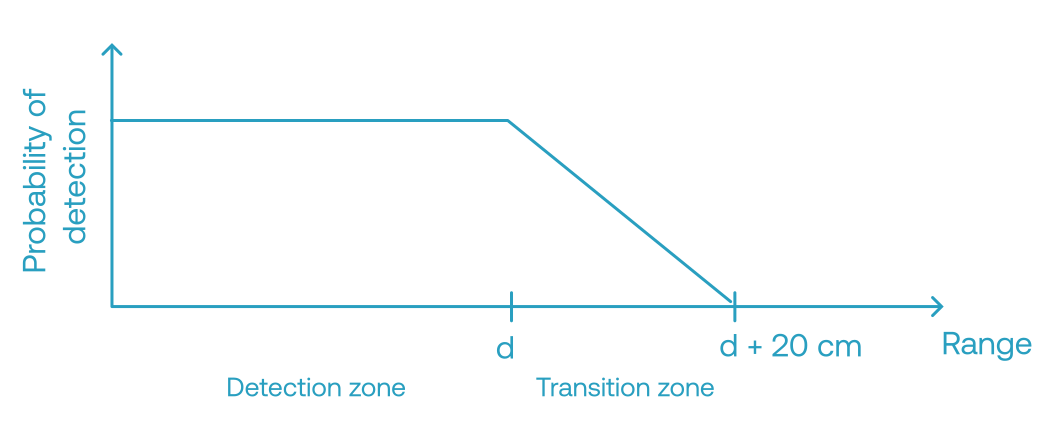
The user can limit the maximum detection range of the sensor from 20 cm to 200 cm.
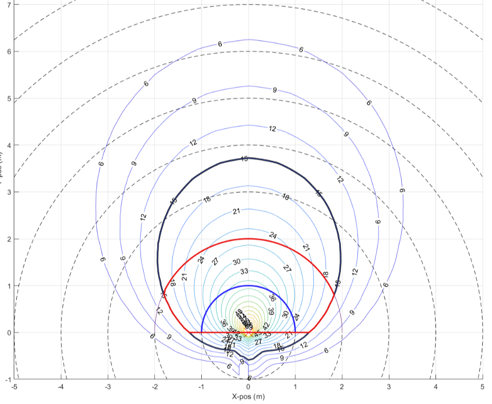
The figure below illustrates the detection zone of the sensor. The blue line shows range set to one meter and the red line shows range set to two meters. As can be seen, the two meter detection zone is limited to the sides of the sensor. This is because the antenna gain in these directions are limited, so even though a typical target is within range, the reflected power will not be sufficient to trigger a detection.
Sensitivity configuration#
The device/user can adjust the sensitivity of the sensor, within a range of level 1 to level 5. This affects the threshold values in the detector, and enables adapting to different kinds of host devices and to different operation environments.
Note
Distance information#
It is possible to read distance information from the sensor. The information consists of the distance to the first hit in mm, and a cluster/window of signal power values positioned around the first hit. The cluster/window makes it possible for host applications to add logic, interpolation, peak detection, etc. to implement more complicated ranging algorithms.
System integration#
Hardware overview#
The Proximity sensor HW is designed to be very easy to integrate into an end product. The sensor communicates with a host processor or MCU through either I2C or SPI serial interfaces Additionally two digital signals are required, sensor enable and sensor interrupt. The sensor can be powered with voltages from 1.8 V to 3.3 V. The sensor HW is SMD capable and provided in reels for simple and automated manufacturing. The sensor is generally robust against materials in front of and around it. For detailed integration guidelines refer to the X4F103 data sheet.
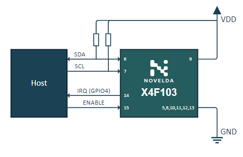
X4F103 Application Circuit with I2C connection#
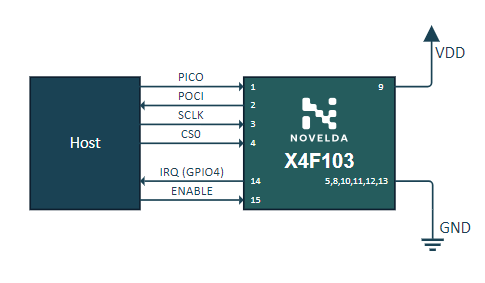
X4F103 Application Circuit with SPI connection#
Software overview#
Block diagram of what SW runs where. Explain interconnects and operation. Rerfer to X4 Sensor Lib UG for details.
Performance#
Power Consumption#
The figure below shows the average power and current consumption for a single radar sweep.
Proximity_Indoor v.1.0.203, VDD = 1.8 V |
||
|---|---|---|
I2C |
SPI |
|
Silence |
1.4 mW / 0.79 mA |
1.5 mW / 0.82 mA |
Presence |
1.4 mW / 0.79 mA |
1.5 mW / 0.82 mA |
The following figures and table shows how much time the radar is in the different modes during one full frame in normal and recording mode during no presence.
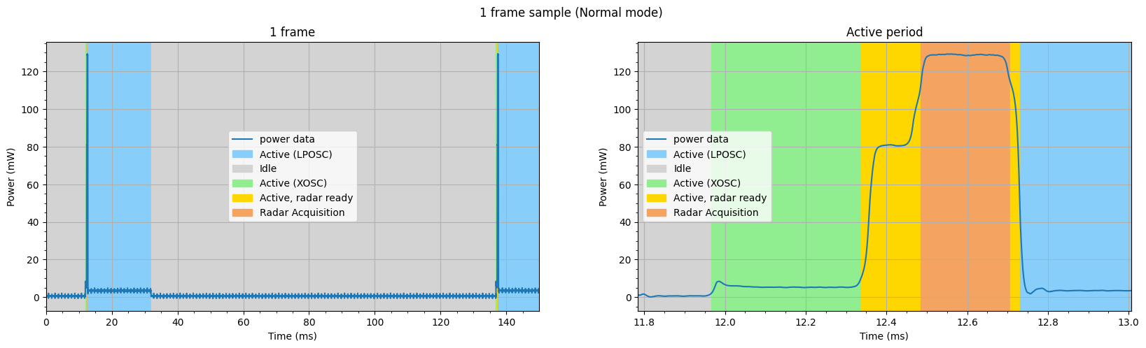
One frame, Normal mode, I2C (Proximity_Indoor)#
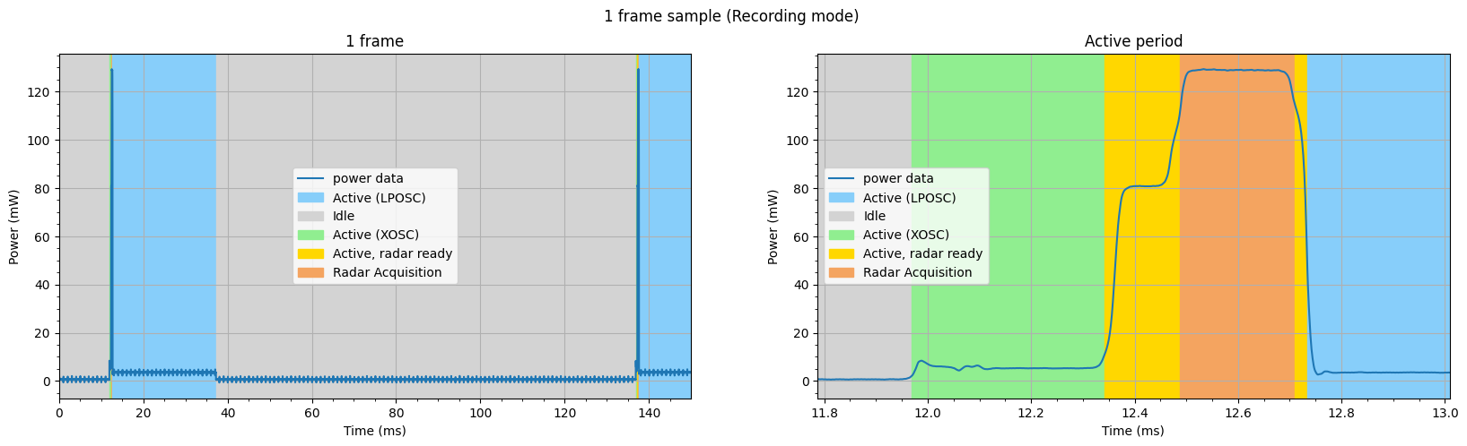
One frame, Recording mode, I2C (Proximity_Indoor)#
Proximity 1.0.203, VDD = 1.8 V |
||||
|---|---|---|---|---|
I2C |
SPI |
|||
Normal mode |
Recording mode |
Normal mode |
Recording mode |
|
1 Frame |
124.89 ms |
124.91 ms |
124.89 ms |
124.95 ms |
Active (XOSC) |
0.37 ms |
0.37 ms |
0.37 ms |
0.37 ms |
Active, Radar Ready 1 |
0.15 ms |
0.15 ms |
0.15 ms |
0.15 ms |
Radar Acquisition |
0.22 ms |
0.22 ms |
0.22 ms |
0.22 ms |
Active, Radar Ready 2 |
0.02 ms |
0.02 ms |
0.02 ms |
0.02 ms |
Active (LPOSC) |
19.23 ms |
24.52 ms |
19.23 ms |
20.18 ms |
Idle |
104.90 ms |
99.63 ms |
104.89 ms |
104.01 ms |
Boot-up time#
Proximity_Indoor v.1.0.203 |
||
|---|---|---|
FW Upload |
1st Sweep |
|
I2C |
116.6 ms |
120.6 ms |
SPI |
51.9 ms |
54.5 ms |
FW upload: Time at fw upload completion since enable goes high (the last interrupt low before 1st Sweep).
1st Sweep: Time at stating sweep since enable goes high (the first radar sweep after starting normal mode).
I2C#
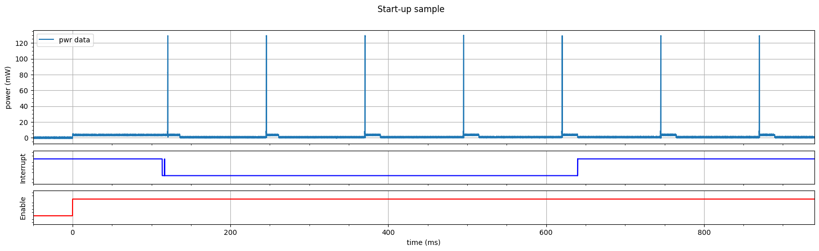
Boot-up sequence for I2C (Proximity_Indoor)#
SPI#
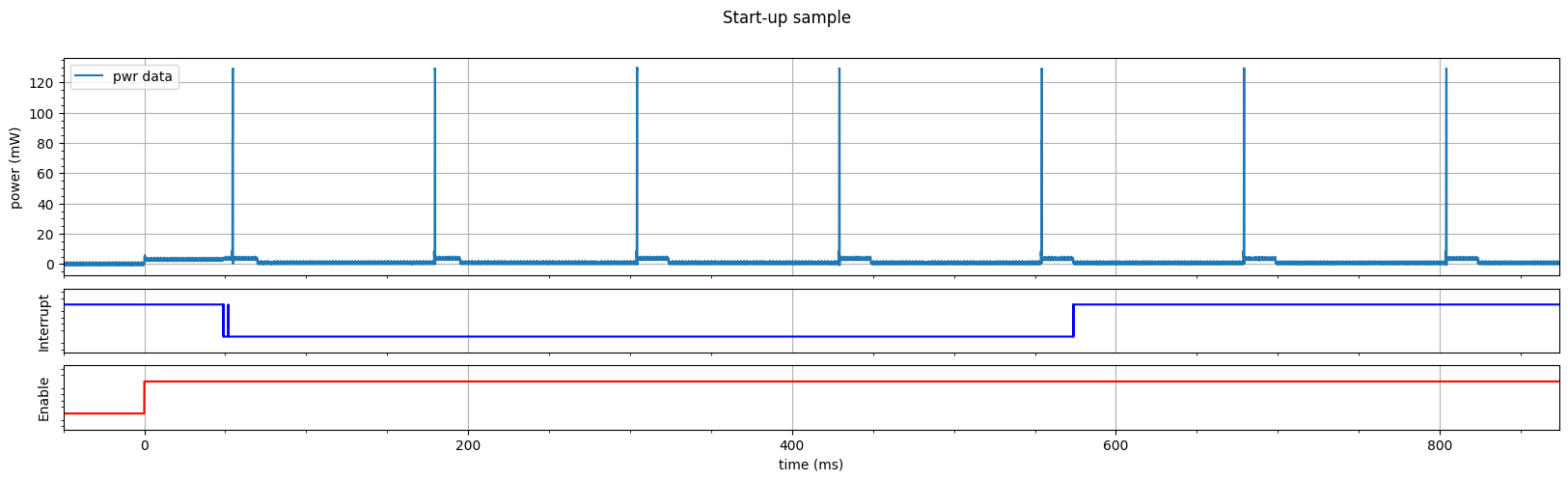
Boot-up sequence for SPI (Proximity_Indoor)#