Occupancy#
Introduction#
The NOVELDA Occupancy algorithm is designed to detect presence of people in various building environments such as homes, offices, parking garages, etc. from a ceiling mounted sensor.
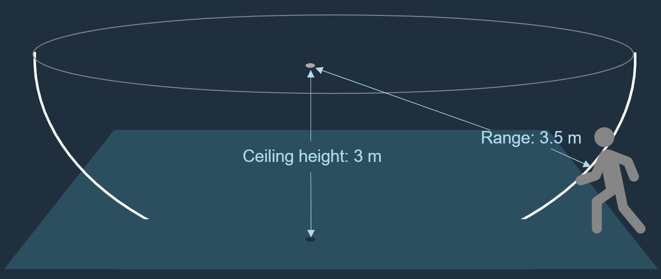
The maximum detection range of the sensor corresponds approximately to a circular zone with a radius of 5 meters. The sensor has absolute range bounding which means that it has full sensitivity out to the configured range limit, and full rejection outside the configured limit.
The sensor is designed to detect major and minor motion, as defined by NEMA. It is also capable of detecting “working motion” which is NOVELDA’s definition of a single person sitting doing typical office work. NOVELDA recommends using a 2 minute hold time in the application logic with the sensor.
Key specifications#
Feature |
Description |
|---|---|
Mounting recommendation |
Ceiling |
Detection capabilities |
Major motion (walking as defined by NEMA), Minor motion (arm moving as defined of NEMA), Working motion (typical sitting/working motion in front of laptop) |
Typical range |
4m line of sight |
Max range |
5m line of sight |
Min range |
1.6m line of sight |
Typical detection latency |
~ 500 ms at 3.6m, highest sensitivity |
Field of View |
~360 degrees (horizontal plane) |
Output |
Detection / No-detection signal |
External host |
No external signal processing required. Only basic MCU to boot and configure the sensor over I2C (8 kB Flash / 1 kB RAM) is needed. |
Power Consumption |
< 20 mW @ 1.8V |
Detection zone#
The sensor has close to 180 degrees vertical field of view and 360 degrees horizontal field of view. The detection range, line of sight from the sensor, can be configured between 1.6 m and 5 m. The resulting detection zone thus has the shape of a half sphere protruding from the ceiling. The sensor detection range should be configured such that the zone encompasses all areas of the room where motion is to be detected.
Sensor operation#
The NOVELDA UWB radar sensor is a pulsed radar system. This means that the sensor transmits electromagnetic pulses that are very short in time (a few nanoseconds) and thus very wide in frequency (hence “Ultra-wide band”). These pulses are reflected from the surrounding environment and the sensor receives and samples the reflections. Pulses are transmitted and received in bursts and multiple pulse samples are used to build a single radar frame which constitutes an image of the surrounding environment at a single moment in time. By repeating this process the sensor provides a continuous stream of data about the environment.
The radar frames are then subject to signal processing to output meaningful data to the host application. This processing is described below.
The transmitted pulse sequences are bi-phase coded which means that the pulses change polarity in a unique pattern. This allows each radar sensor to only receive pulse trains transmitted by itself and thus reducing co-radar interference to practically zero.
Detection algorithm#
The Occupancy sensor algorithm is designed specifically to detect humans with the NOVELDA X4F103 radar sensor. It can be grouped into three main parts: Signal conditioning, detector and application logic. The algorithm is configurable from the host device in two dimensions: Range and Sensitivity.
Signal conditioning#
The signal conditioning stage takes raw RF data from the radar as input. The frames are down-mixed, decimated, filtered and go through noise suppression. The output is signal power in a 1D array where the x-axis is range.
Detector#
The detector logic takes the 1D power array as input. It does thresholding of the signal power and outputs hits, whenever the signal has exceeded threshold values.
Application logic#
The application logic takes hits as input. It performs light-weight logic on the hits to reduce the probability of false alarms. The main parts of the logic check that the hits are consistent over time using binary integration (aka. M-of-N logic). The sensor logic outputs detections to the host device running the user application.
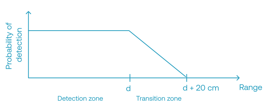
Range configuration#
The maximum detection range of the sensor can be configured from 160 to 500 cm. Range settings above 400 cm are considered experimental and comes with reduced detection accuracy.
Sensitivity configuration#
The sensitivity of the sensor can be configured from 1 to 5. This setting affects the threshold values in the detector, and enables adapting to differences in integration and to different operation environments. Setting 1 is the least sensitive and setting 5 is the most sensitive. The typical setting and the recommended starting point for evaluation and tuning is sensitivity level 3.
Note
System integration#
HW overview#
The NOVELDA Occupancy Sensor runs on the X4F103 sensor module. Refer to the device data sheet for performance numbers and electrical and mechanical details.
The X4F103 sensor module requires the following connections to a host controller:
VDD (1.8 - 3.3 V)
Ground
I2C (2 signals) or SPI (4 signals)
IRQ (interrupt signal)
ENABLE
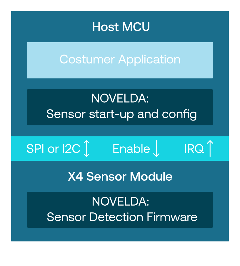
Either I2C or SPI can be used to communicate with the sensor. SPI can run at a significantly higher data rate than I2C (serial clock at 32 MHz for SPI vs 400 kHz for I2C), which leads to faster startup- and reconfiguring times, but requires more physical signals.
The interrupt signal is used by the sensor module to indicate to the host that there is data available to read or that the sensor state has changed, depending on which mode the sensor is in.
Pulling the enable signal low will put the sensor in a low power state. This also completely resets the sensor, including the internal memory. It is recommended to use the provided FW API for doing this rather than controlling the pin directly. It is possible to tie Enable directly to VDD, but it is then recommended to be able to turn VDD off should a sensor reset be required.
The X4F103 is SMD capable and provided in reels for simple and automated manufacturing.
The sensor is generally robust against materials in front of and around it. For detailed integration guidelines refer to the X4F103 integration guideline document.
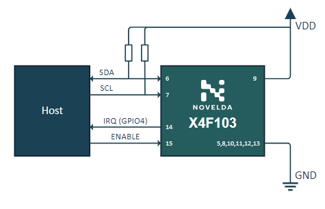
X4F103 Application Circuit with I2C connection#
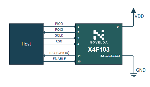
X4F103 Application Circuit with SPI connection#
Software overview#
The X4F103 requires a host controller to store the sensor FW and upload FW and initialize the sensor during boot. After the X4F103 sensor has started it runs autonomously. The host controller is notified through an interrupt signal when needed based on the selected mode of operation.
Sensor interaction from the host controller is provided by a simple driver called NOVELDA X4 Sensor Library.
Host controller minimum requirements#
1 kB RAM, 8 kB Flash, 8 bit MCU
Performance#
Power consumption#
The table below shows the average power and current consumption during continuous radar operation at 20 FPS.
Occupancy v.1.1.2, VDD = 1.8 V |
||
|---|---|---|
I2C |
SPI |
|
Silence |
21.4 mW / 11.75 mA |
21.4 mW / 11.78 mA |
Presence |
21.4 mW / 11.75 mA |
21.5 mW / 11.77 mA |
The following figures and table shows how much time the radar is in the different modes during one full frame in normal and recording mode during no presence.
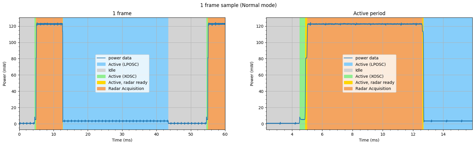
One frame, Normal mode, I2C#
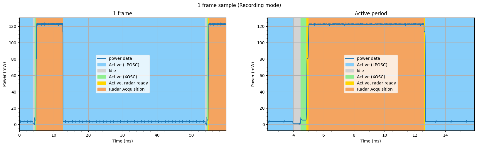
One frame, Recording mode, I2C#
Occupancy v.1.1.2, VDD = 1.8 V |
||||
|---|---|---|---|---|
I2C |
SPI |
|||
Normal mode |
Recording mode |
Normal mode |
Recording mode |
|
1 Frame |
50.04 ms |
49.98 ms |
50.04 ms |
50.04 ms |
Active (XOSC) |
0.38 ms |
0.38 ms |
0.38 ms |
0.38 ms |
Active, Radar Ready 1 |
0.14 ms |
0.14 ms |
0.14 ms |
0.14 ms |
Radar Acquisition |
7.62 ms |
7.62 ms |
7.61 ms |
7.61 ms |
Active, Radar Ready 2 |
0.08 ms |
0.08 ms |
0.08 ms |
0.08 ms |
Active (LPOSC) |
30.73 ms |
41.24 ms |
30.73 ms |
31.76 ms |
Idle |
11.09 ms |
0.52 ms |
11.10 ms |
10.04 ms |
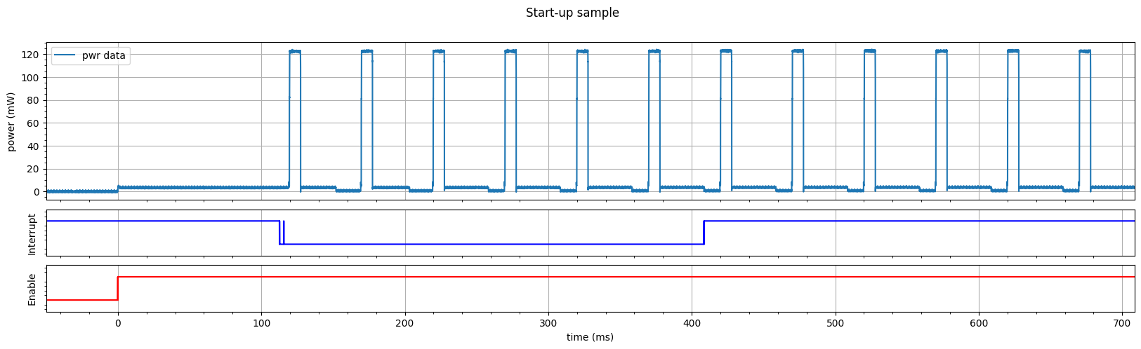
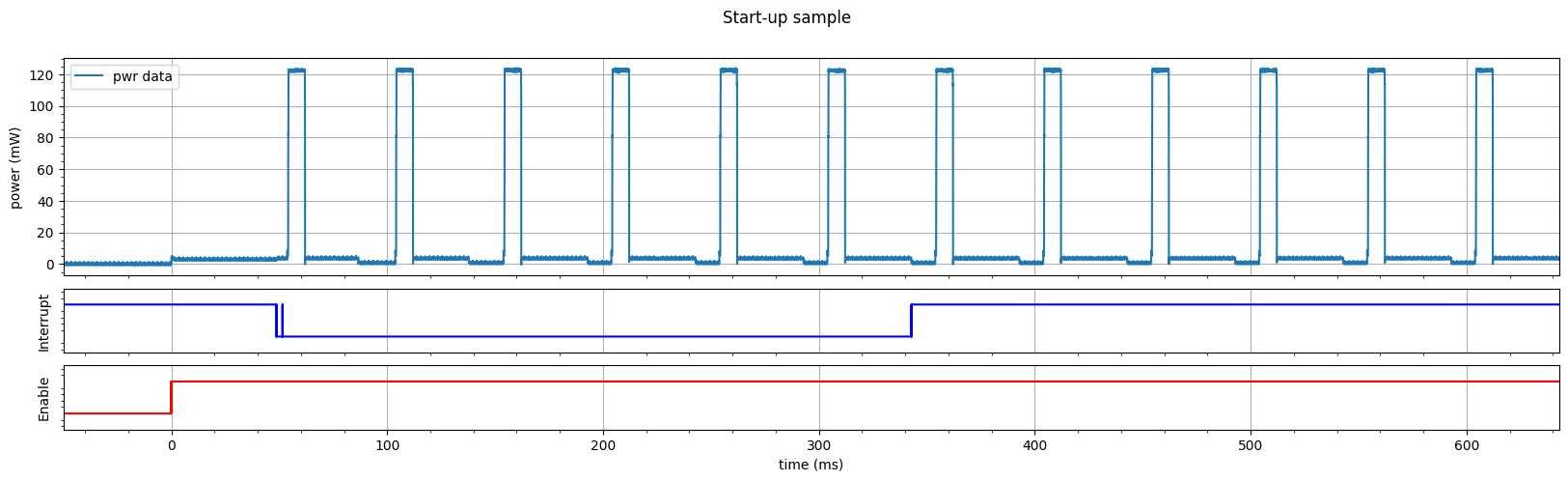
Boot-up time#
Occupancy v.1.1.2 |
||
|---|---|---|
FW Upload |
1st Sweep |
|
I2C |
115.7 ms |
119.6 ms |
SPI |
51.6 ms |
54.2 ms |
FW upload: Time at FW upload completion since enable goes high (the last interrupt low before 1st Sweep).
1st Sweep: Time at starting sweep since enable goes high (the first radar sweep after starting normal mode).
I2C#
Boot-up sequence for I2C#
SPI#
Boot-up sequence for SPI#